Sg3525 Ir2110 Smps Rar Files


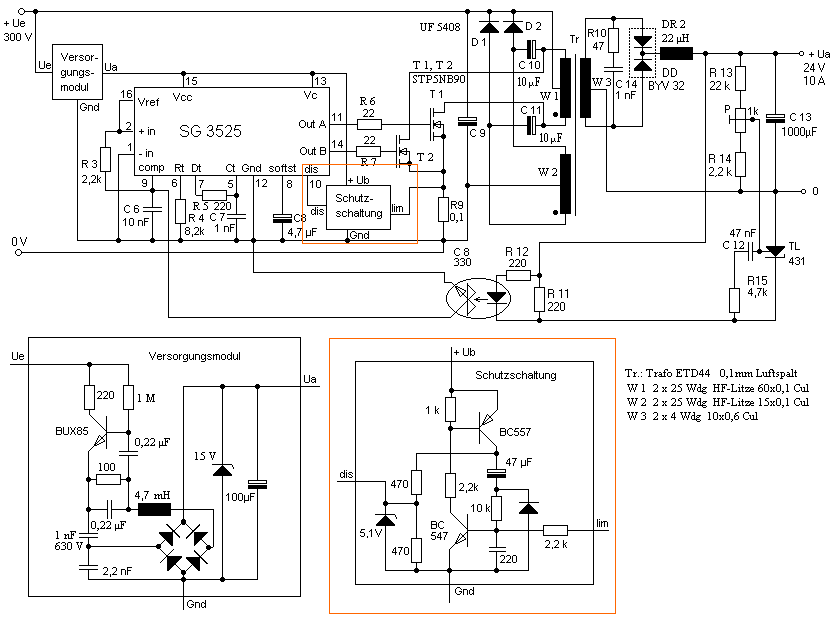
Hello everyone, I made a 50Khz SMPS using the schematic I have attached to my message. I built it using the exact same parts written in the schematic. The only difference is that I adjusted the circuit for +36/-36 volts.
So, I used a 36v zener and as for turns ratio, (Primary 26 turns of 1.7mm ) and (Secondary 2X4 turns of.7mmX5) are my winding. (ExcellentIT calculations) I expected everything to run smoothly but after running it, all I get in the secondary output is +/- 2 volts!! Also the transformer makes an unpleasant noise. What would you suggest me to do? Maybe zenner diodes put reverted?
Feb 8, 2018 - Diysmps >diysmps! >diysmps >SG3525 IR2110 50Khz 900W SMPS Question. Unfortunately, I can't load it from work anymore but, assuming its.
I checked every single part one by one, four or five times. Every thing was correct. So, I recalculated the transformer design and did a new winding. It's a 50Khz half bridge smps with the 300 volts of input voltage. The Rds(on) of IXFH32N50 is.16 ohm.
This SMPS is capable of delivering 864W of power when ETD59 core is used. The primary is 26 turns and secondary is 4 turns X2.
I have regulated 12 volts for SG3525 and IR2110 supply. Diodes I have used for the secondary bridge are BYV79-200 (200v 14A 30ns ultra fast rectifier) Today I noticed that the HISS (saturation noise) is still there even if I connect a load to the outputs. I also tried replacing the 36v zener diode with other voltages. Higher and lower! But nothing changed. I still have only +/-2 volts in outputs. I appreciate your help and attention.
Your feedback and compensation circuits don't looks right but I'm not entirely sure that's your problem. Normally even if it's an unstable feedback loop that oscillates, it will oscillate around the right DC point. Download Aparat Aer Conditionat Alizee Manual Utilizare.
This goes for res_smps too, your simulation is oscillating, presumably from an unstable feedback loop. I'd recommend putting a class Y2 capacitor from primary to secondary ground for starters.
That can eliminate one source of nasty transformer hiss, especially if the hiss changes when you probe it with the scope. I would say if possible, next test it with a fixed duty cycle to see if taking the feedback loop out of the equation makes a difference. Then work on the feedback.
The error amp in the SG3525 is not a transconductance amp, its your average everyday simple voltage feedback opamp and so it is compensated with an RC network from the comp pin to the inverting input, not to ground. What you're doing there is putting a heavy capacitive load on an open loop opamp so it's no wonder it doesn't work. SG3525 is a voltage mode controller, which is right for the half-bridge topology, but typically requires type III compensation which you don't have. SG5325 and IR2110 do make a good combination for an offline regulated half bridge, you don't need to use a 'dedicated half bridge driver' as DjLeco said. The optocoupler complicates this as it introduces an extra pole.
Bias it with a relatively high optotransistor current to increase the frequency of this pole out of the way (above the loop crossover frequency). If I were doing this, I'd use a secondary side TL431 as the error amplifier with its own linearly regulated aux supply so that I could put the type III compensation network there, tie the SG3525's internal opamp so that its output is in cutoff and input the feedback directly to the comp pin.
If you do this, I think you want the optocoupler output to be common-collector. This would be similar to res_smps's 'red circle' schematic assuming he tied the opamp inputs to the correct rails to cut off its output, but C6 there is not a good way to compensate the loop. It just reduces the frequency of the optocoupler pole. If it reduced it well below the LC double pole from the plant that might work as type I compensation but a loop with such low bandwidth would have very poor transient response. If you do use the internal opamp as well the optotransistor would be common-emitter as you have it but there's rarely a good reason to use it in an isolated supply. Here's a brilliant guide to designing TL431/opto isolated feedback. Unfortunately, I can't load it from work anymore but, assuming its the right file, somewhere in there is a type III compensation design guide with a zener regulated secondary aux supply.
Res_smps, I'd advise getting a behavioral model of your secondary side working as a buck converter first with ideal opamps, switches, diodes and latches, then add the transformer, then add the isolation. You can derive a linear model of the buck converter to stabilise it with equations in voltage sources etc and then when you add the transformer, add it in as a turns ratio in the equations, or you can derive a Bode plot of the plant by hand on paper with the equatrions, it's not complicated. Remember to include the ESR of the output cap and any load resistance. SPICE can be a d.o.g (seriously, that's censored on this forum?) for these switching power supplies, so I'd say in your transient simulation command, add a max timestep well below your switching period and add 'uic' on the end of the line. I once spent a week chasing down oscillation that was simply the timestep aliasing on the switching period. Thank you guys.